
In the early 1900s, homemade toys often came with a spark of danger, sometimes literally. Long before modern safety warnings and store-bought science kits, young inventors were encouraged to build their own electrical devices from scraps of tin, wire, cardboard, broom handles, and batteries.
This 1913 article describes how to make a “toy shocking coil,” a small hand-cranked machine designed to give harmless electric shocks to anyone holding the handles.
Though it was presented as a fun parlor amusement for entertaining friends, the instructions offer a fascinating glimpse into the do-it-yourself spirit of the era, when boys’ magazines and newspapers taught children how to experiment with electricity at home.
A Toy Shocking Coil

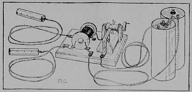
The little shocking machine shown in Fig. 1 is a harmless toy with which you can have an endless amount of fun when entertaining friends. It consists of an induction coil, an interrupter, a pair of handles, and a wet or dry battery. All of these parts are easy for a boy to construct and connect together.
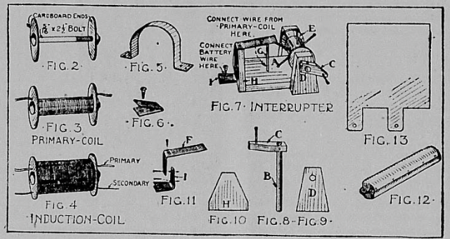
The first part made is the induction coil, which is shown in detail in Figs. 2, 3, and 4. The coil has windings of two sizes of wire upon an iron core. For the core, buy a carriage bolt five-sixteenths of an inch in diameter and two and one-half inches long, and for the wire windings get some No. 20 or 24 gauge electric bell insulated copper wire and some No. 30 gauge insulated magnet wire.
To keep the wire from slipping off the ends of the bolt core, cut two cardboard ends about one and one-half inches in diameter. Slip one onto the bolt next to the head, and the other next to the nut, as shown in Fig. 2. Three layers of the coarse wire is wound on first, and this first winding forms what is known as the primary coil. Pierce a hole through one cardboard end and stick the wire through it and allow about five inches to project upon the outside; then commence winding the wire upon the core, placing each turn close to the preceding turn. When the opposite end of the bolt has been reached, wind back to the starting point, then work back to the other end again.
Cut off the wire so there will be a five-inch projection, and stick the projecting end through a hole in the cardboard end. This completes the primary-coil (Fig. 3). Before winding on the small wire, which forms the secondary coil, wrap the primary coil with a layer of bicycle tape.
Pierce a small hole through one cardboard end, and stick five inches of the fine magnet wire through it. Then wind one the wire as you did the coarser stuff, being very careful to get it one evenly and smoothly. Wind eleven layers on the coil, and run the end of the eleventh layer out through the cardboard end. Fig. 4 shows the completed induction coil.

Cut a base block five inches wide and seven inches long, bevel the top edges to give it a trim appearance, and mount the induction coil to one side of the center, strapping it in place by means of two tin straps similar to that shown in Fig. 5 from a tin can (Fig. 1). The projecting ends of the primary coil connect with the battery, while the two ends of the secondary coil connect with the handles.
Make three binding post plates out of doubled pieces of tin (Fig. 6), and punch a hole through each for a small binding screw. Tack two of these plates to the end of the base and connect the secondary coil wires to them (Fig. 1), and tack the third plate near one end of the induction coil and connect one primary coil wire to it (Fig. 1).
For the shocking handles take two pieces of broom handle three and one-half inches long, and cover each with a piece of tin (Fig. 12). The pattern for the tin covering (Fig. 13) shows how tabs are prepared on the ends and holes punched through them for connecting with the induction coil. The connecting wires should be five or six feet long. Flexible wire is better than bell wire for these, because it is more easily handled in passing the handles around. Tack the tin covering to the pieces of broom handle.
The purpose of the induction coil is to raise the voltage of the battery. The flow of the battery current must be an interrupted one in order to shock, and therefore an interrupter must be inserted between the battery and one of the wires leading to the primary coil of the induction coil. Such an interrupter may be constructed similar to the vibrating armature of an electric bell, but the form shown in Fig. 1, and detailed in Fig. 7, is better suited to our toy machine, and is easier to make and adjust.
Cut the base block A one and one-half inches wide and two and one-half inches long. Make the shaft B two and three-quarters inches long and of a diameter equal to the hole in a thread spool, and prepare the crank C to fit the end and drive a brad into it for a handle. Fasten the crank to the shaft with glue, or by driving a small brad through the two. The axle supports D should be prepared as shown in Fig. 9, one and one-fourth inches wide across the bottom, five-eighths inch wide at the top, and one and three-quarter inches high. Bore a hole through each a little below the top large enough so the axle will turn easily, and fasten these supports with brads to the sides of base A.
Drive eight brads into a thread spool, spacing them equidistant from one another, and mount this spool upon the axle, first slipping the axle through one support, then through the spool, and then through the other support (E, Fig. 7). Drive the spool brads a trifle into the shaft to hold the spool in position.
The projecting arm F (Fig. 7) is a strip of tin cut from a can, and must be long enough so each nail head will strike its end when spool E is revolved. Drive a nail into base A, at G, and after bending the tin strip as shown in Fig. 11, fasten it with brads upon the top of an upright made similar to H (Fig. 10), and nail this upright to the end of base A. The free end of strip F must be bent so it will bear down upon the head of nail G.
The wire from the primary coil which is as yet unconnected should be attached to nail G, and one battery wire should be connected to a binding plate I fastened to the lower end of strip F. Figure 11 shows how the binding plate is made out of a doubled piece of tin, with a hole punched through it for a small binding screw.
This completes the interrupter. Mount it beside the induction coil upon the base block, and connect it with the battery and the induction coil, as shown in Fig. 1. Connect the battery cells in series — that is, the carbon of one to the zinc of the other. Two cells will be enough.
When you turn the crank of the interrupter, each nail in spool E will raise the end of strip G, in passing it, thus breaking the electrical contact. If the strip has been bent properly, it will spring back again into contact with the head of nail G, and each time the contact is made, the person holding the handles will receive a shock.
The strength of the shocks can be regulated somewhat by the speed with which the interrupter crank is turned. The shocks are stronger and more distinct when the crank is turned slowly.
Source: Turner County Herald. Hurley, S.D. October 2, 1913.
You can find Neely Hall’s book, Handicrafts for Handy Boys, on Amazon. (Linked)
