In the early days of radio, building your own receiver did not necessarily require an expensive collection of specialized parts. With a tuning coil, a vacuum tube, a few batteries, and some basic wiring, an amateur experimenter could assemble a regenerative receiver capable of pulling distant voices and music out of the air.
In June 1922, The Indianapolis Times published a remarkably simple design using an ordinary two-slide tuning coil. The setup promised many of the same effects found in more elaborate regenerative sets, including amplification strong enough to bring in distant radiophone stations.
There was also a peculiar side effect. Push the regeneration too far and the receiver would begin generating oscillations of its own, causing distant stations to announce themselves with telltale whistles.
Simplest Regenerative Receiver Made With Two-Slide Tuner

All the thrills which go with owning and operating a regenerative receiver may be experienced at very little expense.
The diagram shows a method of connecting a conventional type of double-slide tuning coil with a vacuum tube and its batteries in such a way as to give access to a fairly broad band of waves while providing an extremely simple means of securing regenerative amplification.
With this arrangement, the vacuum tube may be put through its paces in the same way as though an expensive set were used.
In the specially designed receivers of this type more complete control is provided, of course, but the actions and effects are identical in either case.
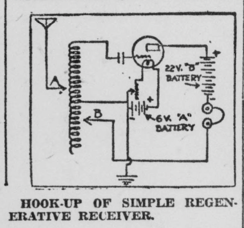
Six-tenths of the way from one end of the tuning coil, take off a tap from one of the wires at a point where the connection will not interfere with the operation of the sliders. Connect the tuning coil as shown, in circuit.
Set slider “B” on the wire from which the tap was taken.
Tune for incoming signals by variation of slider “A.”
When signal is tuned in, advance slider “B” toward the free end of the coil. Amplification will commence and reach an apparent maximum. Still greater strength of signals is to be had, however, by a final simultaneous adjustment of both “A” and “B.”
This circuit may be improved upon by the addition of a variable condenser in the wire which leads to the antenna.
When slider “B” is carried forward too far, the system will begin to act as a generator of oscillations. When in this condition, distant radiophone stations may be located by their “Whistles.”
Source: The Indianapolis Times. Indianapolis, Ind. June 26, 1922.